Secure Your Belongings: the smarter way
If you’ve seen the 1999 Hollywood movie Entrapment starring Catherine 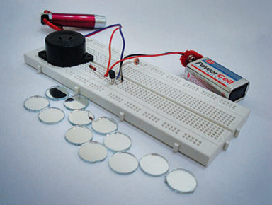 Zeta-Jones, you’ll know exactly what we’re talking about here. No we’re not interested in the attractive female secret agents steering through laser controlled security systems!
We’re excited about the technology that goes along with it. We’re talking about you being able to safeguard your valuables, so that you can enjoy a good night’s sleep.
If someone wants to steal from you, they should at least have a tough time getting past your security shield.
This is how it works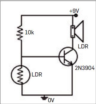
| What you will need:Transistor 2N3904 – 1 no.Capacitor: 1000uF – 1 no.
Laser pointer LDR Resistor: 10K Breadboard Piezo buzzer (3 – 12 V) 9V battery – 1 no. Battery snap A pack of tiny mirrors, commonly available with tailoring shops specialising in embroidery work. Fevikwik for fixing your mirror pieces |
The working principle of the circuit we’re building this month is really simple. What is critical is the set up. Although you’ll find several versions and alternatives available to achieve the same ulterior motive, we’re presenting you this circuit purely for its simplicity and efficiency. It’s so simple you can build it even if you don’t know anything about electronics. 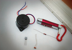
To take you through its working, we use one of those laser key chains that we’re used to seeing while growing up. You use one of the laser pointers and direct its beam at the laser receiver we’re building. The basic component that detects the laser is a simple light dependent resistor (LDR). The laser beam should be incident on the LDR during normal operation of the circuit. In the event of an intrusion, the laser network that you’ll create using tiny mirrors is obstructed. The LDR detects this obstruction and in conjunction with the transistor interprets it as a change in state. The resultant change in electrical signals triggers the buzzer to alert anyone around you of the ongoing theft attempt. Vigilant neighbors and friends are all you need to foil the intrusion attempt.
Identifying your components
The picture alongside gives you a glimpse of the components you are going to use for this DIY. The buzzer has two wires – one red and the other blue. Connect the red wire to the positive terminal, and the other wire to the negative terminal. The transistor is an NPN transistor and has three terminals known as collector, base and emitter. You can identify the terminals from the photo or you can also refer to a datasheet. If you place the circular side of the case to the left (resembling a C), with the flat side to the right and the terminal facing down, then the terminal towards you is the emitter. The terminal in the middle is the base and the terminal on top is the collector. i.e. The terminal on top of your C is the collector, the middle is the base and the terminal on the base of your C is the emitter. The LDR or light dependent resistor has two terminals with a wavy line on it.
 Connecting the components together
You can start with a breadboard to test this project so that you don’t get frustrated if it doesn’t work. As you can see, the circuit is very small and simple. With just three components in it, you should be able to get it without any prior knowledge of electronics.
To start, place the transistor on the breadboard, as shown in the photo – the flat side facing you. If you’d try and recollect now, the terminals from left to right are emitter, base and collector. Connect the LDR between the two terminals to the left of the transistor (base and emitter). Connect the buzzer between the third terminal of the transistor (collector) and a new point X on the board. To this point, connect one terminal of the resistor (10K). The other terminal of the resistor connects to the collector of the transistor. To the common point between the resistor and the red wire of the buzzer, connect the red wire (positive) of the battery. Similarly, connect the black wire (negative) of the battery to the emitter of the transistor.
 You’re done…really!
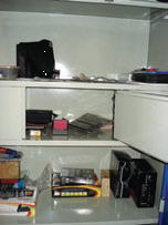
Believe it or not, half your work is done. Although, by way of constructing the circuit you’ve completed your job. Now, you are left with craft work literally. Strategically place the mirrors such that they are not easily visible and create a mesh of LASER around your valuables. We prefer mirrors because other reflective materials tend to dissipate or distort the beams, thereby causing problems with the sensitivity of the circuit. There’s no limit to the network you could form by the mirrors. All you need to do is ensure that the beam finally falls on the LDR in normal circumstances. This way your buzzer will be off in normal state. If you want a more permanent solution, solder the components together and keep the LDR concealed so that the LASER beam is not seen.


