PC Temperature Monitor
When we’ve bought ourselves a brand new computer, we tend to take good care of it; ensuring temperatures don’t rise beyond the recommended level. Sooner or later we tend to take our computing marvel for granted, suck as much as we can from it, till it finally comes to a standstill refusing to budge this time!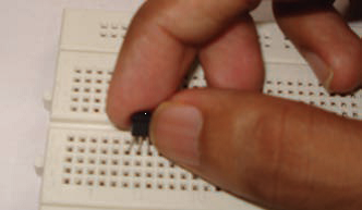
All of this could be avoided with corrective and preventive measures taken before hand. For one, most people find it inconvenient to repeatedly go to the BIOS of their system to check the processor and cabinet temperature. Again, installing software purely for diagnostics is unfortunately perceived as a waste of system resources. Popularly, users would rather have the system informing them of critical milestones.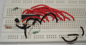
What to expect
The primary objective of this circuit is to inform you of the temperature of its vicinity, so that you can take precautionary measures. IC LM35DZ is a precision Celsius temperature sensor. It converts ambient temperature into an equivalent analogue voltage. This analogue signal is translated into an equivalent bar graph by the bar/dot graph driver IC LM3914. Ten LEDs form the bar graph. We recommend using three colors – green, yellow and red to depict the bar graph. Green indicating normal operational temperature, yellow is indicating the warming up phase and red approaching breakdown point.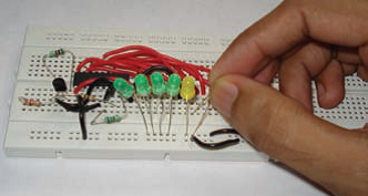
| What you will need |
| CapacitorsC1 – 1uF / 25V Electrolytic
C2 – 10uF / 25V Electrolytic Resistors R1 – 2.2k R2, R5, R7 – 1k variable resistor R3 – 1k R4 – 1.5k R6 – 470 ohms
R8 – 100 ohms Diodes D1-D10 – LEDs ICs U1 – LM35DZ Precision Centigrade Temperature sensor U2 – LM3914 Bar/Dot Graph driver IC Miscellaneous Breadboard, connecting Wire, wire cutter/stripper, 9V battery, batteries snap
|
Assembly
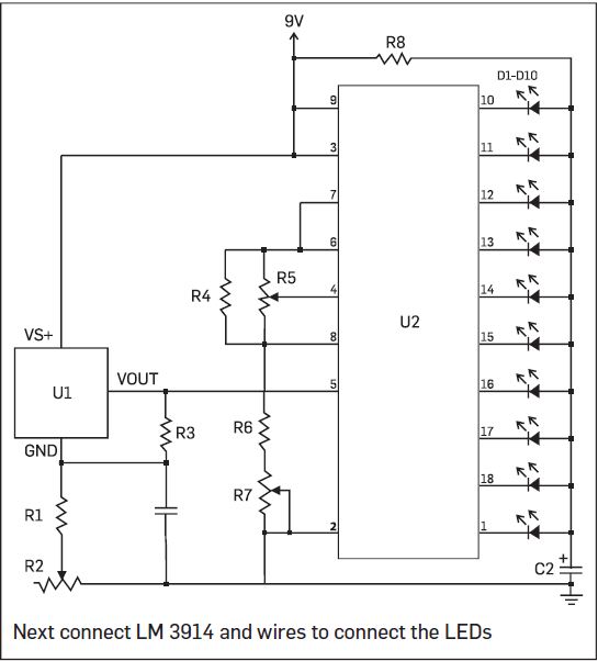
Refer to the circuit diagram. Begin with temperature sensor LM35DZ. If you look at the bottom side with the pinsfacing you and the flat side facing up, then the terminals from left to right are: +Vs., Vout and GND. Begin by placing the sensor on the breadboard as shown in the figure. Next place ICLM3914. As you can see from the circuit diagram, you need to connect an array of 10 LEDs to the IC, one to each pin. For this, draw wires from pin nos. 1 and 10 to 18, as shown in the image. The anodes (longer terminal) of the LEDs are all connected together via resistor R8 to positive of battery. The three potentiometers are connected in three different ways. R2, connected after R1, uses only two terminals (the third terminal is left open). Similarly, R7 also uses only two terminals, but the second and third terminals are connected together. R5 uses all the three terminals as shown in the circuit diagram.
Please ensure that the negative terminals of the electrolytic capacitors are connected to the negative terminal of battery. Reversing the orientation of the capacitors can cause malfunction. This circuit has two modes of operation – bar mode and dot mode. In the bar mode, the LEDs light up resembling a bar graph. Similarly, in the dot mode, the corresponding LED lights up, referring to the specified temperature. Before you can operate the circuit, you need to calibrate it so that it operates in a linear
way. Make all the connections, connect the battery and switch the circuit on. Keep it on for a couple of minutes, so that the circuit stabilizes. Measure the voltage at pin 7 of IC2. For this set your multimeter to DCV. Keep the black probe connected to the negative terminal of the battery and the red probe connected to pin 7 of IC2. Vary resistor R7 so that the voltage at pin 6 and 7 stabilizes at around 3.345V. Similarly, adjust R5 so that the voltage at pin 4 stabilizes at 2.545V.
Now disconnect the battery, remove both ICs from the breadboard and vary R2 such that the resistance across R1 and R2 should be three times the value of R3. For example, if you measure R3 and instead of 1k, it measures 990 ohms, then you need to adjust R2 so that R1 (approx. 2.2k) and R2’s value would add up to 2.99K. Reconnect the ICs in the circuit, switch the power on, and the LED should light up as shown in the figure.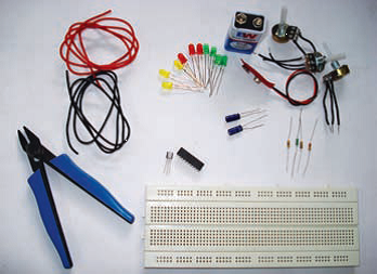
Although we’ve taken steps to ensure that the circuit presented here is functional, several factors are beyond our control. In order to avoid malfunction and to avoid dead ends, we recommend assembling the circuit on a breadboard before finally soldering on a circuit board. Procure components as per the list. The project presented here is purely for educational/ entertainment purposes only. We take no responsibility for any loss arising either directly or indirectly as a result of use or implementation of this project.
| Disclaimer |
| Although we’ve taken steps to ensure that the circuit presented here is functional, several factors are beyond our control. In order to avoid malfunction and to avoid dead ends, we recommend assembling the circuit on a breadboard before finally soldering on a circuit board. Procure components as per the list. The project presented here is purely for educational/ entertainment purposes only. We take no responsibility for any loss arising either directly or indirectly as a result of use or implementation of this project. |


